Deformable Terrain
- DEVOPS
Learn about a terrain similar to the Earthwork Zone, but that is built to achieve better performance on large deformable areas.
Deformable Terrains are used to define a terrain that can be deformed or piled with soil. They are defined using a bounding box that intersects with a Graphics Gallery (the visuals of a terrain). Alternatively, they can be created by converting an existing Earthwork Zone or by importing a height map.
Deformable Terrains are diggable (meaning that soil can be removed and the terrain can be deformed). A Deformable Terrain supports Earthwork Tools and features.
Creating a Deformable Terrain
From an Existing Earthwork Zone
A Deformable Terrain can be created from an Earthwork Zone that has already been set up. The visuals and behavior will be similar once converted.
- Open your scene that contains an Earthwork Zone.
- In the Explorer panel, navigate to the Earthwork Zone.
- Right-click the Earthwork Zone and select Convert to Deformable Terrain.

The Earthwork Zone will disappear and a Deformable Terrain will be added to the scene.

From a Graphics Gallery
A Deformable Terrain can be created from scratch using a Graphics Gallery as the initial shape and visuals.
- In a new scene, add a Graphics Gallery from the Toolbox. Preferably, this Graphics Gallery is a textured, uneven and relatively horizontal surface, such as the
Construction_Site.vxgraphicgalleryfound in theDemo Scenes\Environment\Construction_site\Graphicsfolder of your CM Labs Content folder. The root node of the Graphics Gallery will be the basis for the Deformable Terrain.
- From the Toolbox, add Environment > Deformable Terrain. Hovering over the Deformable Terrain in the Explorer panel will reveal a message warning you that a Soil Materials Extension is required to function properly.
- In the Toolbox, select Earthwork Systems > Soil Materials.
- In the Explorer panel, expand the Deformable Terrain, then select the Deformable Terrain to display its Properties panel.
- In the Deformable Terrain's Properties panel, under Parameters > Terrain Nodes, press the + button to add an empty row.
- With the Deformable Terrain root object still selected in the Explorer panel, and the Graphics Gallery expanded, drag and drop the Terrain Node from the Graphics Gallery to the empty Terrain Nodes row you just created in the Deformable Terrain Properties panel.

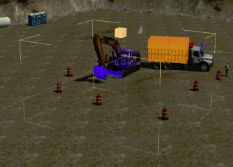
Your scene should look something like this:
- In this instance, the bounding volume of the Deformable Terrain is not large enough to capture the lowest parts of the Graphics Gallery. Use the Resize manipulator to sink the lower bounds of the Deformable Terrain to encompass the Graphics Gallery.

- In the Toolbox, select Basics > Add Mechanisms From Files.... In this example, select the
Excavator.vxmechanismfile found in theDemo Scenes\Equipment\Excavator\Dynamic\Designfolder of your CM Labs Content folder. - Press the Play button, and control the excavator to dig into the Deformable Terrain. You will see that the ground deforms properly but the deformed surface is white, with no particles or soil in the bucket.
- In the Toolbox, select Earthwork Systems > Soil Particles. Soil will now accumulate in the bucket and particles are visible.
- In the Toolbox, select Graphics > Texture to add an albedo layer (
Loam_DIFF.png) and a normal layer (Loam_Normal.png), found in theDemo Scenes\Equipment\Resources\EarthworkSystems\Loamfolder of your CM Labs Content folder. When importing, select the Compress Textures option. - From the Toolbox, select Graphics > Material to add a graphics material. Select it in the Explorer panel to open its Properties panel. In the Properties tab, expand the Normal category and click the + button to add a normal layer. With the Material properties still shown, drag the
Loam_DIFFtexture to the Albedo > Texture field, and theLoam_Normaltexture to the Normal > Texture field. - With the Deformable Terrain expanded in the Explorer panel, select the Terrain Graphics extension to open its Properties panel.
- Expand the Deformed Material Layer section.
- From the Explorer panel, drag the newly-created Material into the Material field in the Deformed Material Layer section.
- Refer to the Soil Particles Extension to properly texture the particles.
- Press Play again.


From a Terrain File
The steps to create a Deformable Terrain from a Terrain file are nearly identical to creating from a Graphics Gallery.
- From the Toolbox, select Environment > Terrain From File....
- Select the relevant Terrain file.
- Follow the same procedure (starting with step 2) as outlined in From a Graphics Gallery above.
From a Height Map
A Deformable Terrain can be created from scratch using only a height map provided from disk. It involves additional steps but gives greater control to the user.
From the Toolbox, select Graphics > Texture. Add the following textures to your scenes (save them directly from this page). When importing deselect the Compress Textures option:


Height Map Albedo - From the Toolbox, select Environment > Deformable Terrain.
- In the Explorer panel, expand the root object of the Deformable Terrain.
- Drag the height map you added from the Explorer panel into the Height Map field in the Deformable Terrain's Properties panel.
- From the Toolbox, select Graphics > Material to add a graphics material. Select it in the Explorer panel to open its Properties panel.
- From the Explorer panel, drag and drop the albedo texture you added above into the Albedo field of the Material's Properties panel.
- Select the Deformable Terrain's Terrain Graphics extension in the Explorer panel.
- In the Undeformed Material Layer > Material field, select the material you added in the Explorer panel.
Press Play to see the following result.


Height Map Deformable Terrain Same terrain but with SkyDome, Adaptive Feature Controller, and shadow casting enabled on the Terrain Graphics
Note that white indicated the lowest possible point in the height profile on the terrain, and is used to define not-deformable regions. If soil should be deformable in these regions, the color should not be exactly white but just slightly gray.
Modify the Size, Resolution and Position of a Deformable Terrain
Deformable terrains can be moved and resized. Their Cell Size can also be changed (from 0.1 m to 0.05 m for example). Lower resolutions will have more detail but at a higher performance cost, and larger sizes will have higher performance costs, as well.
The default parameters for a deformable terrain is 100 m x 100 m, with 0.1 m cell size. You could expect similar performance from a terrain that is 50 m x 50 m with a 0.05 m cell size.
When selected during editing, the deformable terrain will appear with the corners outlined, as seen below.
|
| Deformable terrain while selected |
|---|

When you select the Resize tool for the deformable terrain, it appears with a bounding box. You can resize the box by pulling on the indicator points on each side.
|
| Deformable terrain in Resize mode |
|---|

A deformable terrain can also be resized via its Dimensions and Cell Size parameters.
When selected, the deformable terrain's area is outlined for viewer's clarity.
|
| Deformable terrain with outline showing when simulating |
|---|

Modify the Appearance of a Deformable Terrain
It is recommended to use different materials for the deformed and undeformed layers of a terrain. You can use the captured layers outlined in the Building Blocks section below as starting point for the undeformed layer and Vortex Studio's sample materials as starting point for the deformed layer (found the Demo Scenes folder of your CM Labs installation folder).
- Start by following the instructions earlier in this topic to convert the Excavator Demo Scene (found the Content folder of your CM Labs installation folder) to a Deformable Terrain. Look closely at the added soil layer mound. For the purpose of this document, we will make it look like a pile of gravel.

- In addition to the current scene, open the material sample Graphics Gallery file from the Vortex Studio Demo Scenes folder, found at
CM Labs\Vortex Studio Content <version>\Demo Scenes\Materials\MaterialsLibrary_6.8.vxgraphicgallery.
Note that this Graphics Gallery contains a number of sample materials. These may change from one version to the next.
- Copy the 2K Gravel material and paste it in your scene.

- Select the Terrain Graphics extension in the Explorer panel. In its Properties panel, assign this material to Deformed Material Layer > Material.
- Press Play.

- Change the coverage to 5 m so the gravel looks more coarse and less fine.


Details of a Deformable Terrain
This section serves as a reference of technical terms for Deformable Terrain and an overview of its built-in components.

Building Blocks
The Deformable Terrain is a combination of multiple Vortex extensions, most notably the Terrain Graphics, Terrain Dynamics and Terrain Capture. Users should normally only need to interact with the Deformable Terrain root object.
The connections are responsible for distributing values from the root object to the Child Extensions.

The Captured Material is responsible for the initial look of deformable terrains created from a Graphics Gallery, File Terrain or Earthwork Zone. It can be copied and edited or reused elsewhere in your scene.
 |  |
| Captured Material | Captured Material Setup |
|---|
Finally, the Terrain Hole extension is responsible for hiding File Terrains and Graphic Galleries over which a deformable terrain is superimposed.
Data
There are five captured layers when creating a deformable terrain from a Graphics Gallery, Earthwork Zone or File Terrain.
 |  |  |
 |  |
- The Captured Depth Buffer is used to shape the physical and graphical surface of the terrain. Without it, the terrain would be all flat.
- The Captured Color, Normal, Specular and Occlusion Buffers are used to create the graphics material. Without them, the terrain would be all black.
Each Capture can be copied and reused elsewhere in your scene.
There is one runtime-updated buffer.

The Deformed Layer is used to track which area of the soil has been disturbed from its initial state. This is used to determine whether the undisturbed texture (Terrain Graphics > Undeformed Material Layer) or disturbed texture (Terrain Graphics > Deformed Material Layer) should be drawn on a particular area of the terrain. This can be used to capture the effect of a wet underlayer of soil that appears different than the dry top layer.