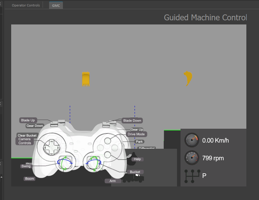
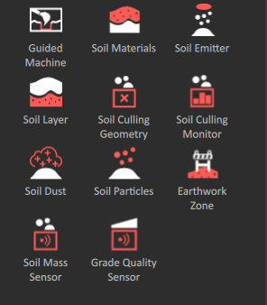
Guided Machine Control Display
- DEVOPS
Simulate machine control systems and GPS displays for earthmoving equipment, such as excavators, wheel loaders, and dozers.
Many heavy equipment manufacturers offer Global Positioning (GPS) and Guided Machine Control (GMC) systems which integrate positioning data for the bucket or blade with topographical maps of a job site and satellite data to automate and guide earthmoving operations. GPS and GMC systems can integrate with work monitor displays and Human Machine Interfaces (HMIs) to show status information for an excavation operation and give operators visual feedback.
The Guided Machine Control extension in Vortex Studio is designed to simulate GMC and GPS Heads-Up Displays (HUDs) that integrate with current earthmoving equipment. To simulate GPS and LIDAR data sources, Vortex Studio calculates the distance between cutting tools and grade targets during your simulations.
With the GMC extension, you can replicate the GPS/GMC HUD and show it to your users (see Creating User Interfaces (UI) ). By defining Vortex Studio collision geometries and graphical nodes, you can represent grade control targets and cutting blade tools for simple and complex digging surfaces.
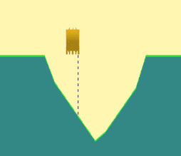
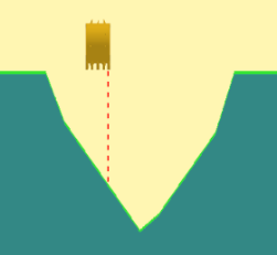
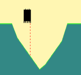
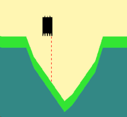
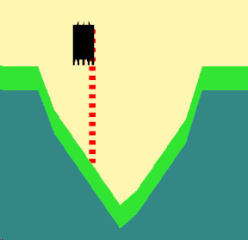
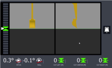
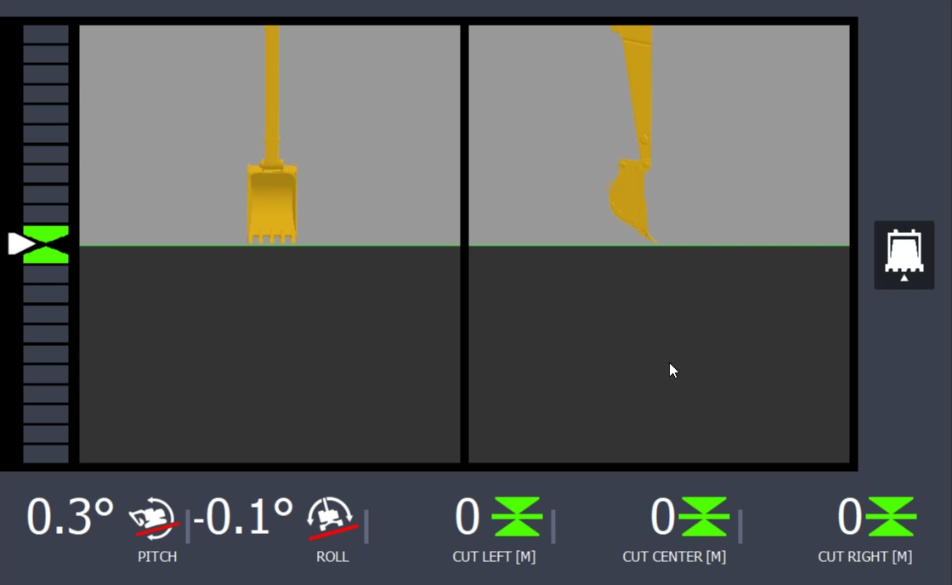
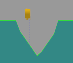
Example of a GPS HUD for an Excavator Generated Using the Vortex Studio Guided Machine Control Feature
Getting Started... | Tell Me About... |
Setting Up the Guided Machine Control Extension
NOTE: The steps in this overview use images and references that you can find in the Excavator Demo Scene, installed with Vortex Studio. Demo Scenes can be found in C:\CM Labs\Vortex Studio Content <version>\Demo Scenes\Scenario\Excavator Scene.
Setting up a Guided Machine Control HUD for your equipment simulation typically involves the following activities:
- Specifying the area of your earthworks zone that you want to appear on the HUD.
For example, if you have a scene where an excavator operator needs to excavate part of the terrain to a specific depth, you would specify that the HUD only shows the area of the scene where the digging operation occurs.

See instructions for: Specifying an Area of the Scene to Show on the HUD
- Using Collision Geometries (CGs) to model the target grade surfaces that the extension will use as height and depth thresholds during earthmoving operations and placing the model in the correct location within the area you define for the HUD.
For example, if you have a scene where an excavator operator needs to use the bucket to excavate a v-ditch, you can use CGs to model the v-ditch you want the operator to create and place it inside the area you define for the display. The Guided Machine Control extension uses the CG model of the v-ditch as a reference to show the position of the bucket and excavated material in relation to the correct specifications of the model.

See instructions for Modeling the Target Grade Surface for the HUD.
- Adding a connection interface to define how the cutting tool transform sends information to the corresponding graphical node that the system uses for the Guided Machine Control HUD.

See instructions for Creating a Connection Container for the Cutting Tool Transform.
- Customizing and adding the HUD to your user interface pages.
See instructions for Adding the HUD to the Viewport.
- Adding the display to a Console user interface page for simulator users.
See instructions for Setting up a Console Page for the Guided Machine Control HUD.
Specifying the Area of the Scene to Show on the HUD
NOTE: The steps in this overview use images and references that you can find in the Excavator Demo Scene, installed with Vortex Studio. Demo Scenes can be found in C:\CM Labs\Vortex Studio Content <version>\Demo Scenes\Scenario\Excavator Scene.
To show the position of the cutting tool in the Guided Machine Control HUD with accuracy, Vortex Studio uses system resources that can impact the frame rate of your simulation. For best performance, you must restrict the area you show on the HUD to the place in the Earthworks Zone where operators do work with the cutting tool.
Specifying the area that the viewport shows on the HUD involve adding the extension to your scene and configuring how the HUD will show the position of the cutting tool in relation to the grade targets or thresholds you will define in later steps.
Prerequisites: Before you begin, you must have a scene that includes a defined Earthworks Zone with a diggable area and a mechanism with a cutting tool, such as a bucket or blade, that you want to show on the HUD.
To add the Guided Machine Control extension, do the following:
- Open the scene where you will specify the area the HUD will show.
- Go to Toolbox > Earthwork Systems and add the Guided Machine Control extension to your scene.
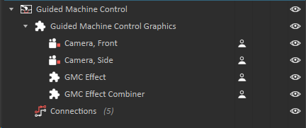
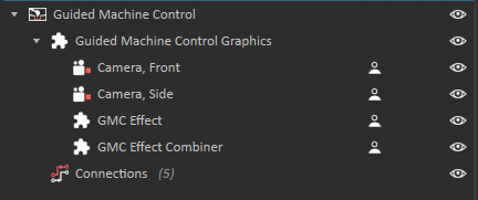
- In the Explorer panel, expand the Guided Machine Control extension to show all the sub-extensions.
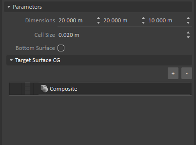
- To prepare for the target surfaces you will define for the HUD, in the Properties panel, under Target Surface CG, use the list control to add a new target surface CG.
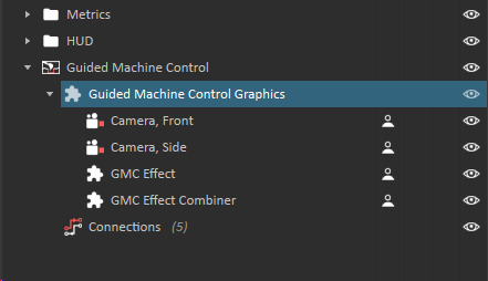
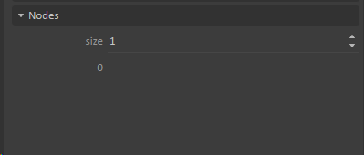
- In the Explorer panel, click to select the Guided Machine Control Graphics extension.
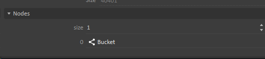
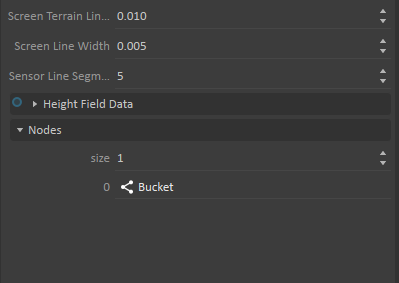
- To prepare for display geometry that you will configure later, in the Properties panel for the extension, under Nodes, set the size field to 1.
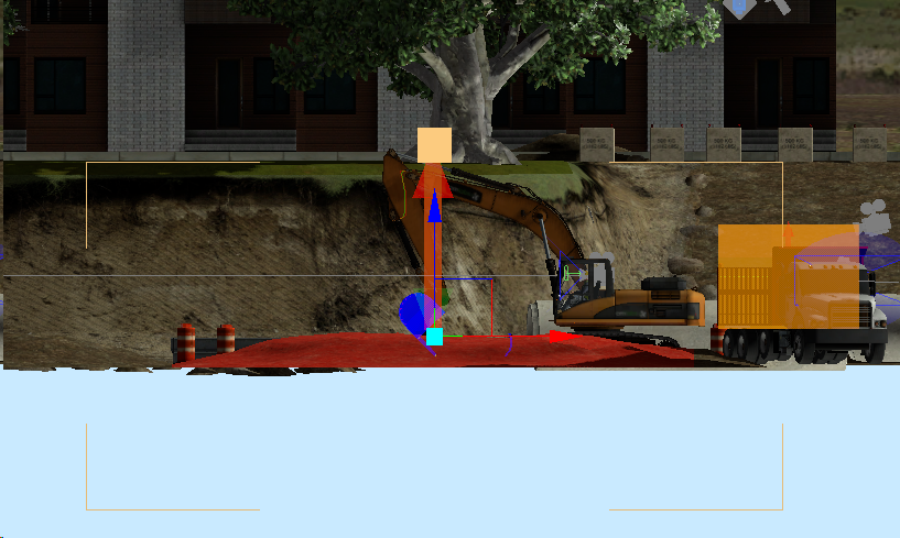
- Use controls to position the Guided Machine Control accessory in a location that overlaps your Earthworks Zone.
Make sure that the top of the accessory is as near to the surface of the terrain as possible.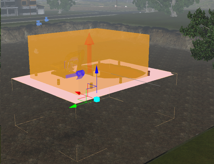
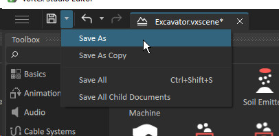
- To save your work, click the Save menu arrow and then click Save as. Give the file a meaningful name.
TIP: It is easier to adjust the position of the accessory in a side view.
Modeling the Target Grade Surface for the HUD
NOTE: The steps in this overview use images and references that you can find in the Excavator Demo Scene, installed with Vortex Studio. Demo Scenes can be found in C:\CM Labs\Vortex Studio Content <version>\Demo Scenes\Scenario\Excavator Scene.
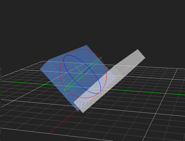
Typical target surfaces for a Guided Machine Control HUD include slopes, v-ditches, and elevation offsets. To model a complex target surface, you can use multiple collision geometries (CGs). For a simple surface, such as a v-ditch, you can define a single composite CG.
The following procedure gives steps for defining a single composite CG for a v-ditch.
To Define a Target Surface for the HUD
- Open the scene that you added the Guided Machine Control extension to.
- Create an empty mechanism. In the Explorer panel, double click the mechanism to edit it.
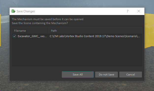
- Save all your changes.
- In the empty mechanism, create a new empty assembly. To edit it, in the Explorer panel, double click on the new assembly.
When prompted, save the document.
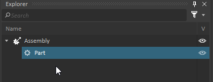
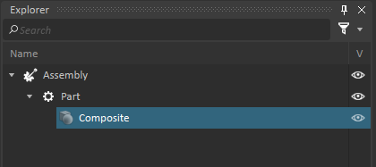
- In the Assembly Editor, add a new part to the Assembly. The document hierarchy appears as follows:
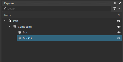
- Add a new Composite CG to the Part
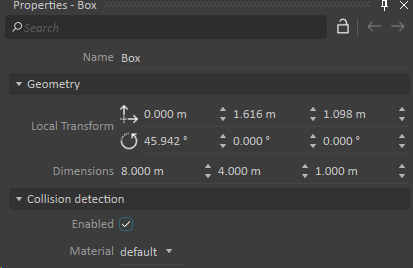
- Create a new Box CG. Set its dimensions to 8m x 4m x 1m.
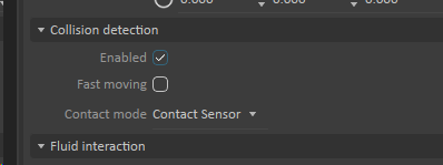
In the Properties panel for the Box CG, Under Collision Detection, click to select Enabled.
- Duplicate the Box CG.
- In the Properties panel for the composite CG, Under Collision Detection, click to select Enabled. In the Contact mode drop-down menu, select Contact Sensor.
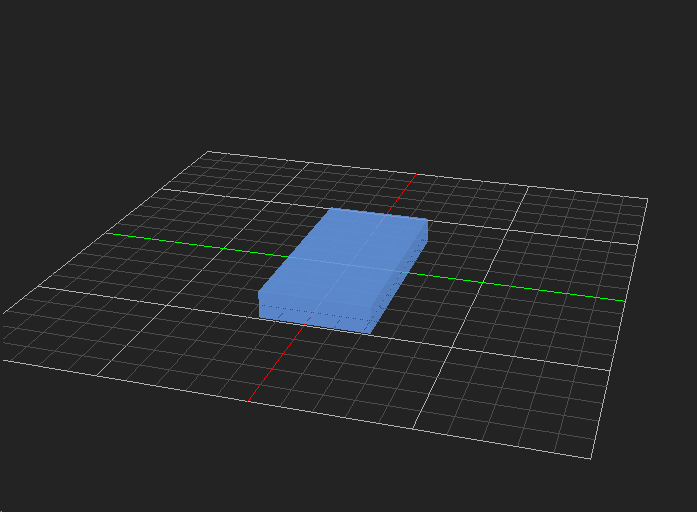
- Use controls to arrange the Box CGs (not the Composite CG) until they form a V-ditch shape. The shapes must overlap.

- Click in the Explorer tree to select the Part.
- To make it so that you can interactively place the CG in the scene during editing, do the following:
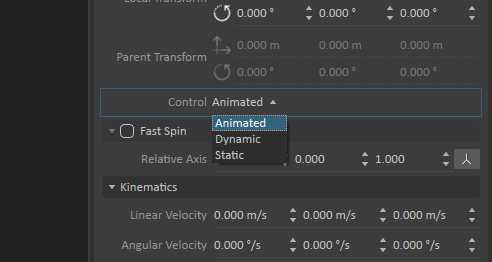
- In the Properties panel for the part, under Inputs, find the Contact field.
- Use the drop-down menu to set the Contact field to Animated.
- Save your changes and then return to the main scene.
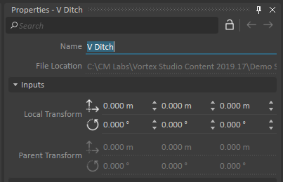
- For identification purposes, rename the mechanism to V Ditch.
- In the Explorer panel, click to select the V Ditch mechanism. Click the visibility icon
 to show available display filters and click to select Geometry.
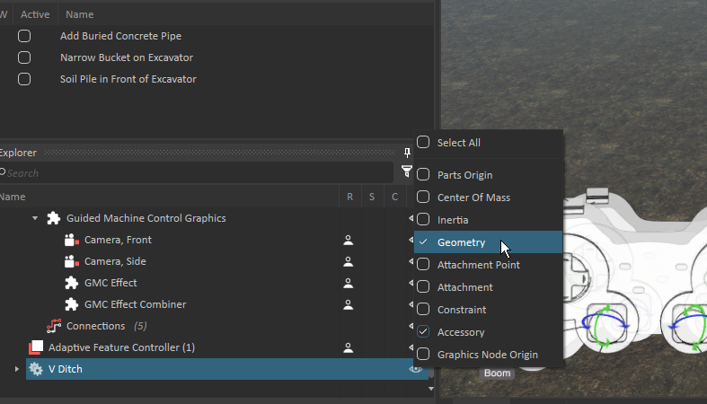
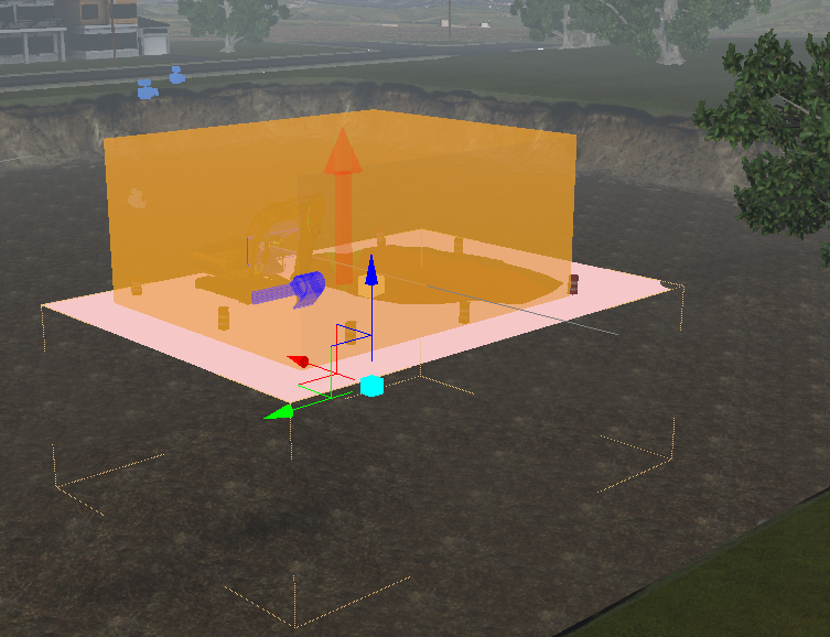
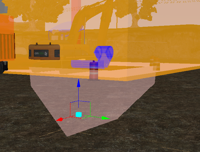
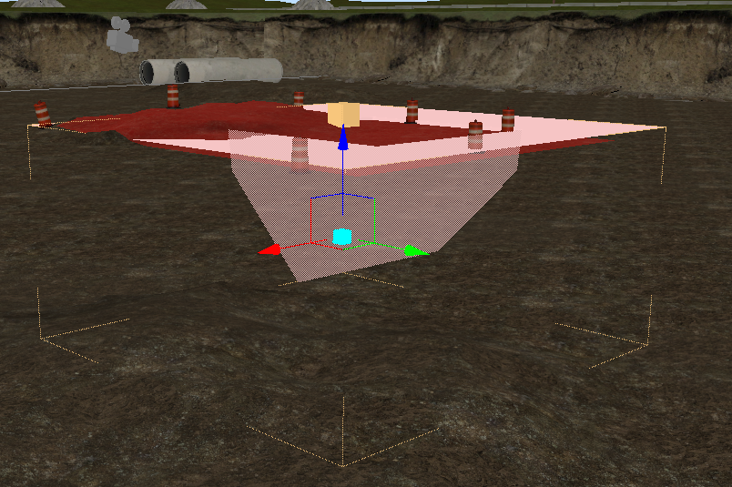
The V-Ditch is displayed in the viewport.
- Use controls to place the V Ditch mechanism in a location that is completely inside the bounding box of the Earthwork Zone Accessory, below the ground level. If necessary, you can modify the dimensions of the Earthwork Zone and Guided Machine Control accessories.
Adding the Guided Machine Control HUD to a Viewport
NOTE: The steps in this overview use images and references that you can find in the Excavator Demo Scene, installed with Vortex Studio. Demo Scenes can be found in C:\CM Labs\Vortex Studio Content <version>\Demo Scenes\Scenario\Excavator Scene.
To add the Guided Machine Control HUD to your viewport during runtime, you must do the following:
- Click to select the Guided Machine Control extension.
- Under the V-Ditch mechanism, click to select the Composite CG and drag it into the Properties panel, to the Target Surface CG field that you added in the procedure for setting up the extension.
- To see the projection of the shape, press the simulate button.
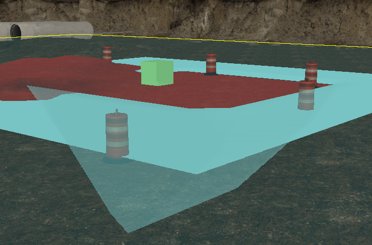
- Verify that the volume in the viewport matches the shape of the V Ditch CG.
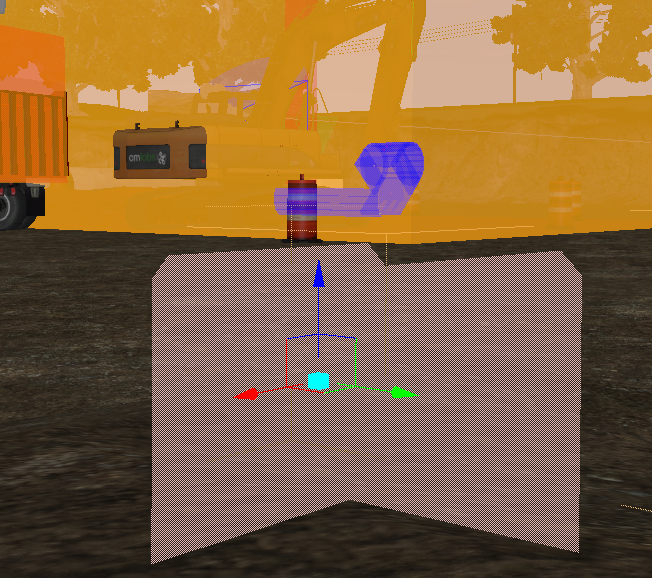
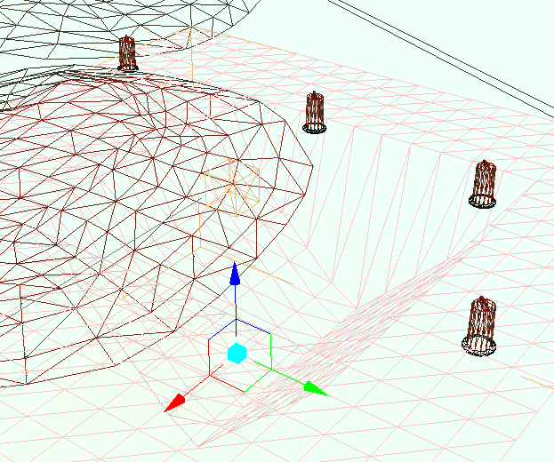
- To show the soil surface more realistically, in the Properties panel, under Parameters, click to select Bottom Surface.
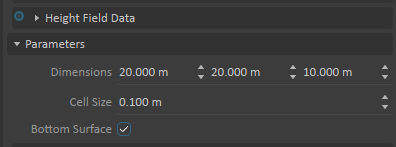
The system shows the projection from the top down (instead of from the bottom up).
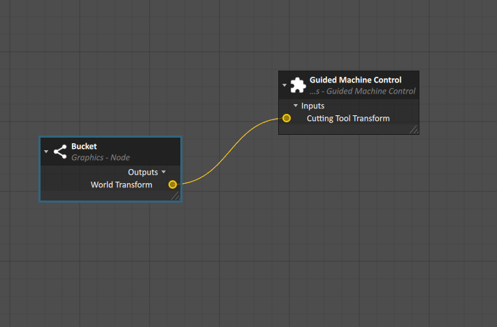
- In the Explorer panel, find the graphical node for the cutting tool (in this example, named Bucket). Drag the node into the Properties panel of Guided Machine Control Graphics Extension, under the Nodes section.
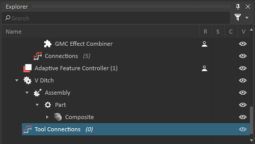
- In the Explorer panel, create a new Connection Container extension and rename it Tool Connections.
- To connect the Bucket Node and the Guided Machine Control extension Cutting Tool input, do the following:
- Add the World Transform output for the Bucket node to the graph.
- Add the Cutting Tool Transform for the Guided Machine Control extension to the graph.
- Create a connection between the World Transform output and the Cutting Tool Transform input.

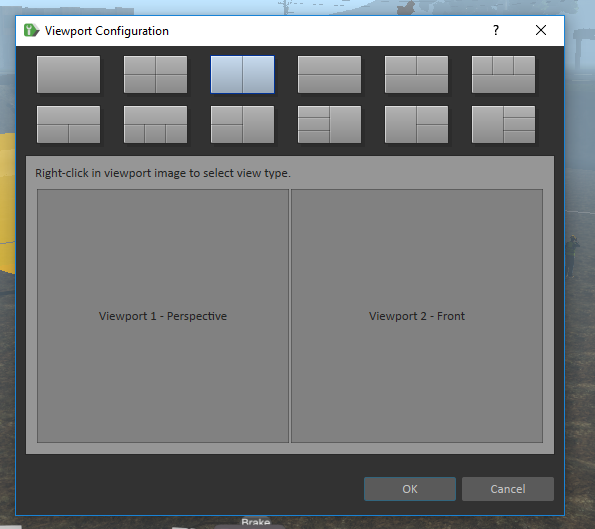
- Set the Viewport Configuration to Split mode.
- Click to select the Guided Machine Control Graphics extension.
- In the Properties panel, under Inputs, set Target Viewport Name to Viewport 2.
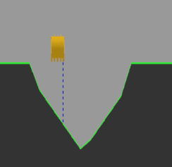
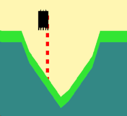
- To see the HUD during the simulation, maximize Viewport 2, and start the simulation. The HUD appears as follows:
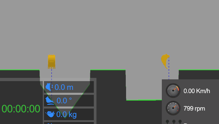
IMPORTANT: If you notice that the excavator help or user interface block the view of the HUD, you can hide or delete those extensions.
Setting up a Console Page for the Guided Machine Control Display
To make the Guided Machine Control HUD appear on a simulator screen, you must embed it in a QtDesigner page that users can see on a Console interface.
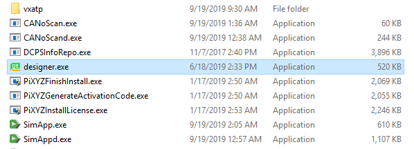
- To open Qt Designer, navigate to the bin folder of your Vortex Studio installation directory and launch the designer.exe executable. file.
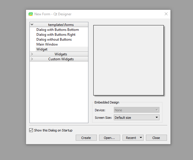
- Create a new Qt Designer widget form.
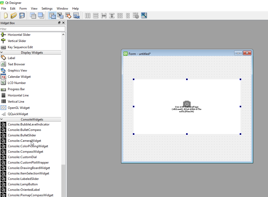
- On the left side panel, under Console Widgets, click to select Console:: CameraWidget and drag it into the new widget form.
- Save the form.
- Add a Label widget with the text Guided Machine Control to the upper right of the Camera widget.
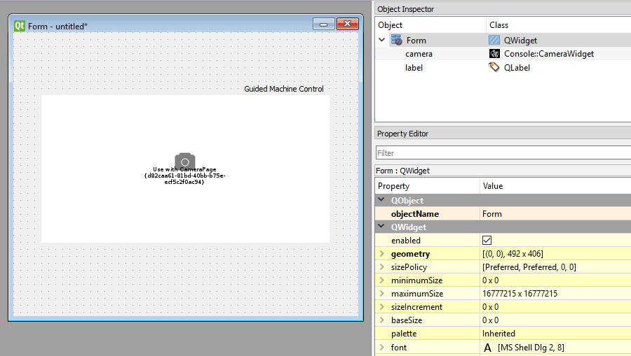
- Verify that the objectName of the Camera widget is
camera. - Save the form and exit the Qt Designer application.
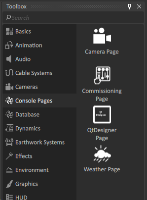
- In the Vortex Studio Editor application, create a new mechanism, and add a Camera Page extension to it.
- In the Properties panel, under Parameters, find the UI File field and click the browse button to select the Qt form for your Camera widget.
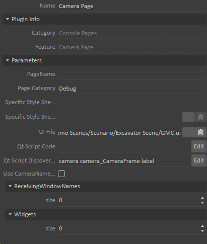
- Save the mechanism with a meaningful name. For example,
cam_page_mechanism.
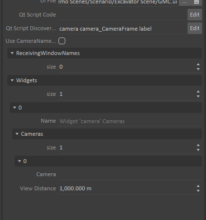
Property fields for the mechanism are automatically updated. - In the Properties panel, under Cameras, set the size field to 1.
- Under Parameters, in the PageName field, type
GMC.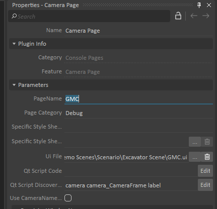
- Close the mechanism file.
- Open the scene file that you added the Guided Machine Control extension to.
- Add a Camera Page Mechanism to the scene and rename it to
Camera Page Mechanism.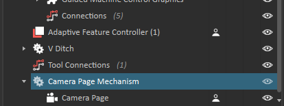
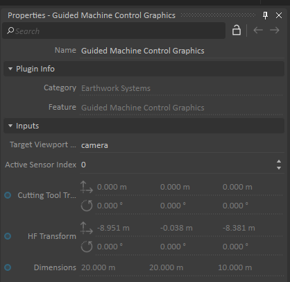
- To connect the target viewport in the scene to the camera Qt object you created, click the Guided Machine Control Graphics extension. In the Properties panel, under Inputs, set the Target Viewport to camera.
- Navigate to the Console tab and then click the GMC tab.
NOTE: Because of the way the Excavator Demo scene is designed, the view overlays other UI elements over the Guided Machine Control HUD.

- Start the simulation.
The movement of the excavator bucket (the cutting tool) is represented in relation to the V-Ditch CG you added in the Guided Machine Control HUD.
Guided Machine Control Extension Reference
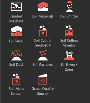
In the Vortex Studio Editor, you can find the Guided Machine Control extension in the Toolbox with other Earthwork Systems extensions.
It includes child extensions for setting up the graphics components and connections the application needs to show information correctly.
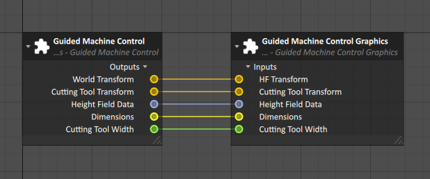
Guided Machine Control Extension Details
The Guided Machine Control extension controls the dynamic properties of the cutting tool and terrain that you want to simulate for the HUD.
| Input | Description |
|---|---|
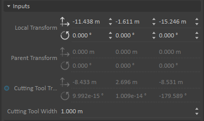
| Local Transform | The local transform specifications for the area of terrain in the HUD. |
| Parent Transform | The parent transform of the area you specified for the HUD, relative to a parent transform. |
| Cutting Tool Transform | The world transform by the cutting tool. The node position typically determines values for this input.
|
| Cutting Tool Width | The width of the cutting tool. The width of the cutting tool affects the placement of raycast sensors that the system uses to show positioning information.
|
| Output | Description |
|---|---|
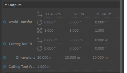
| World Transform | The world transform of the entire accessory |
| Cutting Tool Transform | The current cutting tool transform |
| Dimensions | The current dimensions of the area of the earthworks zone that you specified for the HUD. |
| Cutting Tool Width | The current width of the cutting tool. |
| Distance Measurements | Various outputs with information about the number of sensors and the distances between them. Each sensor is identified by a number (1-n) |
| Size | The current number of sensors on the cutting tool. |
| Start Position | The start position of the casting ray for that sensor on the cutting tool. |
| End | The position where the casting ray meets the height field. |
| Distance | The distance between the Start and End Positions |
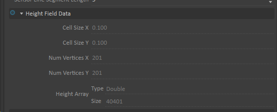
| Height Field Data | Various outputs with information about the cell size, vertices, and height array of the height field. |
| Cell Size X | The x component value of the heightfield cell. |
| Cell Size Y | The y component value of the heightfield cell. |
| Num Vertices X | The number of vertices in the x dimension of the heightfield. |
| Num Vertices Y | The number of vertices in the y dimension of the heightfield. |
| Height Array Type | The numerical type of heightfield elevation data. |
| Height Array Size | The total number of heightfield elevation vertices. |
| Parameter | Description |
|---|---|
| Dimensions | Defines the volume of the guided area.
|
| Cell Size | Defines the cell size of the heightfield.
IMPORTANT: The size of the heightfield can affect performance. |
| Bottom Surface | Select the check box to make the application sample the heightfield starting from the bottom of the area you specified for the HUD to the target surface collision geometries.
|
| Target Surface CG | Specify collision geometries that define the surface of the area the HUD will show.
|
Guided Machine Control Graphics Extension Reference
The Guided Machine Control Graphics sub-extension controls how the system visually represents the cutting tool, target surfaces, and background on the HUD.
| Input | Description |
|---|---|
| Target Viewport | The viewport where the HUD will appear. If you use a Camera page for the UI, enter the object name of the QT camera widget. |
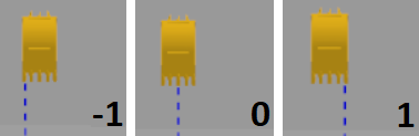
| Active Sensor Index | The sensor index values (-1,0, and 1) that application uses for information about the position of the cutting tool on the display.
|
| Cutting Tool Transform | The cutting tool transform values, derived from the Guided Machine Control extension Cutting Tool Transform output. Modifying these values can cause problems in the extension.
|
| HF Transform | The heightfield transform values, derived from the Guided Machine Control extension World Transform output. Modifying these values can cause problems in the extension.
|
| Dimensions | Defines the volume of the area that the HUD displays, derived from the Guided Machine Control extension Dimensions output.
|
| Cutting Tool Width | The width of the cutting tool, derived from the Guided Machine Control extension Cutting Tool Width output.
|
| Flip Side Camera | Click to select or clear the check box to specify the orientation of the side camera that the extension uses.
|
| Flip Front Camera | Click to select or clear the check box to specify the orientation of the front camera that the extension uses.
|
| Terrain Line Color | Controls for specifying the color of the upper boundary of the heightfield in the HUD. You can specify the color with RGB values or click on the color selector.
|
| Terrain Volume Color | Controls for specifying the color of terrain under the boundary of the height field in the HUD. You can specify the color with RGB values or click on the color selector.
|
| Background Color | Controls for specifying the color of the background in the HUD. You can specify the color with RGB values or click on the color selector.
|
| Sensor Line Color | Controls for specifying the color of the sensor line projection to the heightfield in the HUD. You can specify the color with RGB values or click on the color selector.
|
| Bucket Color | Controls for specifying the color of the projected sensor line in the HUD. You can specify the color with RGB values or click on the color selector.
|
| Screen Terrain Line Width | Controls for specifying the width of the terrain line. You can specify a numerical value or use arrows to change the value.
|
| Screen Line Width | Controls for specifying the width of the projected sensor line. You can specify a numerical value or use arrows to change the value.
|
| Sensor Line Segment Length | Controls for specifying the length of each segment in the projected sensor line. You can specify a numerical value or use arrows to change the value.
|
| Height Field Data | Controls for specifying the visual attributes of the height field.
|
| Nodes | The specific graphics nodes that the visualization displays.
|