Configuring the Vehicle's Dynamics
 This procedure describes how to connect the power-train to the chassis, which is a crucial step in setting up your vehicle properly.
Open the mechanism where you have defined the vehicle and added a vehicle preset for it if it is not already open.
Note If you have not already added a vehicle preset, follow the instructions under Creating a Vehicle from a Vehicle Preset.
From the Explorer panel, expand the vehicle preset icon under the Vehicles folder and click on the Vehicle Preset extension.
The Properties panel now displays the dynamics properties for the vehicle preset.
The Vehicle Preset property page contains a large amount of parameters under many sections. To help manage the large of data, you can hide (collapse) the sections you are not using. For example, these procedures only affect the parameters under the Parameters section.
Under the Parameters > Chassis section, click the Browse button in the Part reference box.
The Select Part dialog box appears, as well as the Odometer Starting Value field, where you can specify the starting odometer distance in kilometres.
From the Explorer Panel, click the chassis part.
The chassis part's name now appears in the Select Part dialog box.
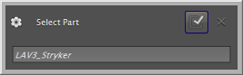
Click the Confirm button on the Select Part dialog box. The chassis part's name now appears in the parameter box.
After connecting the power-train to the chassis, you can configure any of the features covered in this section.
Ackerman Steering
Steering for wheeled vehicles versus tracked vehicles is different: wheeled vehicles use Ackerman steering by default, whereas tracked vehicles use differential and skid steering controllers.
Note Ackerman steering operates only on wheel components with Steerable parameters enabled.
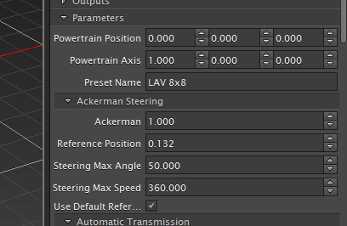
You can access the parameters to customize Ackerman steering by expanding the Ackerman Steering section nested under Parameters. For example, some of the parameters you may need to adjust include:
- Ackerman, which you can change to a negative number to use Reverse Ackerman, or set to
0to disable. - Reference Position, the reference point on the vehicle's longitudinal axis.
- Steering Max Angle, which must be set at least once.
- Steering Max Speed, which sets the limit for how fast (in radians per second) the angle can be changed.
- Whether to Use Default Reference Position or use the value specified in Reference Position.
Automatic Transmission
Some presets come with a Parameters > Automatic Transmission section, found in the Dynamics component's Properties panel, which allows you to define the speed at which the gears are changing, and the efficiency of the torque converter.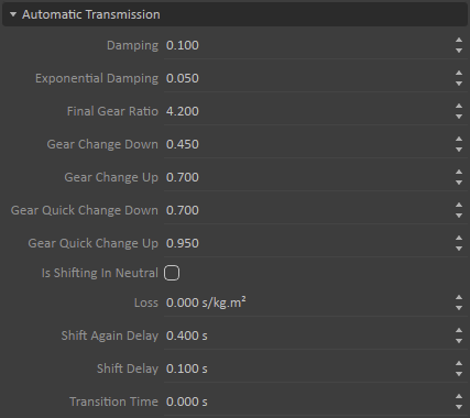
- Damping: Defines how friction determines transmission power loss
- Exponential Damping: Defines a velocity exponent determining transmission power loss
- Final Gear Ratio: The final gear ratio between the transmission and the sprockets. This value changes the total transmission ratio (which is calculated from the this value and the current gear ratio).
- Gear Change Down: The point at which the transmission shifts down. The value represents the ratio of the input shaft speed RPM of the transmission to the engine's maximum RPM.
- Gear Change Up: The point at which the transmission shifts up. The value represents the ratio of the input shaft speed RPM of the transmission to the engine's maximum RPM.
- Gear Quick Change Up: See Quick Operation Mode.
- Gear Quick Change Down: See Kickdown.
- Is Shifting in Neutral: See Transition Time below.
- Loss: A tuning parameter that allows the relaxation of the internal Vortex® constraint in cases where the simulation is unstable. In general, this value is zero.
Shift Again Delay: Sets a time delay (in seconds) during which the transmission can't shift again. The total time during which the transmission can't shift is the sum of the Shift Delay and Shift Again Delay values.
Unlike the period of time defined by the Shift Delay parameter, the differential is enabled during this period of time.- Shift Delay sets a time delay (in seconds) during which the transmission goes to neutral during a shift.
- Transition Time is the time taken to make the transition between two successive gears. If Is Shifting in Neutral is selected, the transmission goes into neutral during this time.
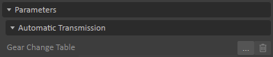
In addition, nested under the Parameters > Automatic Transmission section is the Gear Ratios section. See Gear Change Table below for more information.

Note If a Gear Change Table is used, its relevant values override those specified above.
Quick Operation Mode
When the normalized throttle position is between 0.5 and 1.0, the up shift point moves to a higher value compared to the normal operation mode in order to delay the shift, allowing a longer period of time on the current gear. In this case, instead of shifting at the Gear Change Up value, the shift occurs at:
![]()
Where rpmq is the Gear Quick Change Up value, rpmup is the Gear Change Up value, τ is the current throttle position (whose normalized range falls within 0.0 and 1.0).
Kickdown
The transmission does a "kickdown" (i.e., a quick downshift) when the throttle position is rapidly floored and if the RPM ratio is below the Gear Quick Change Down value. In kickdown mode, the transmission shifts up like in Quick Operation Mode.
For the transmission to shift up and down properly, RPM and gear diameters must respect certain conditions as expressed by the following:
![]()
Where Ri,i+1 is the ratio between two consecutive gear diameters. Note that during run time, the Quick Operation Mode rpm value is used instead of rpmup i in the above formula.
Gear Change Table
Within Parameters > Automatic Transmission, the Gear Change Table field that specifies the path to a CSV file where you can set each gear's RPM change values.
An example of a CSV file's format is as follows:
| Gear Change Table | |||
| Gear Change Up | Gear Quick Change Up | Gear Change Down | Gear Quick Change Down |
| 0.7 | 0.95 | 0.45 | 0.7 |
| 0.7 | 0.95 | 0.45 | 0.7 |
| 0.7 | 0.95 | 0.45 | 0.7 |
| 0.7 | 0.92 | 0.45 | 0.67 |
| 0.7 | 0.9 | 0.45 | 0.64 |
| 0.7 | 0.87 | 0.45 | 0.61 |
| 0.7 | 0.85 | 0.45 | 0.61 |
The amount of rows must be equal to the number of gears, starting with reverse gear(s), then neutral, followed by the forward gears. These rows correspond to the Gear Ratios fields, found under Parameters > Automatic Transmission > Gear Ratios.
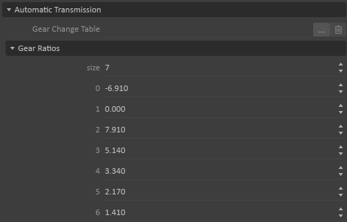
The Gear Ratios section is where you can add and remove gears as needed by adjusting the size parameter and changing the ratio for each gear independently. These ratios correspond to the diameter of each gear. A negative value denote a reverse gear, and a zero value represents neutral.
In the above Gear Change Table example, the first row refers to Gear Ratio row 0, a reverse gear given its negative value. The second row of the Gear Change Table is actually a neutral gear, since Gear Ratio row 1 has a zero value. The remaining rows of the Gear Change Table represent forward gears since their Gear Ratio values are greater than zero.
Note Not all values of the table are used. For instance, if this table is meant for a transmission with one reverse gear, Gear Ratio row 1 (the second row) is not used. Likewise, Gear Change Down values are not used for the reverse gear (because there is no gear below it to shift down to) nor for Gear Ratio line 2 (the third row) since you can't automatically change down from first gear to neutral. Similarly, the Gear Change Up values are not used for the reverse gear going into neutral, nor the final forward gear.Also, there is no direct shifting between reverse and forward gears.
Manual Transmission
Some presets come with a Parameters > Manual Transmission section, which allows you to define how the gears synchronize when changing.
- Damping defines how friction determines transmission power loss
- Exponential Damping defines a velocity exponent determining transmission power loss
- Final Gear Ratio is the final gear ratio between the transmission and the output shaft. This value changes the total transmission ratio (which is calculated from the this value and the current gear ratio).
- Max Torque sets the maximum torque allowed when the shift is engaged.
- Synchro Speed Tolerance sets the synchronization speed tolerance in radians per second. This tolerance allows the gear to be shifted even if the shafts are not strictly equal.
- Synchro Time sets the transmission's synchronization time in seconds.
- Synchro Torque sets the transmission's synchronization torque, applied when shifting to synchronize the input and output shaft speed.
In addition, nested under the Parameters > Manual Transmission section is the Gear Ratios section, where you can add and remove (forward) gears as needed by changing the size parameter and change the ratio for each gear independently.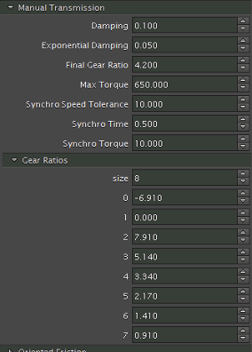
In addition to the parameters in this section, there are a few other sections that are important to manual transmissions. These include:
- Clutch, where you can set the clutch max torque (usually from 10 to 20% of the maximum engine torque)
- Hand Brake, which allows you to set the Maximum Brake Torque that can be applied on each wheel.
- Start Engine Logic, which allows you to define what happens when the engine starts, specifically how much time the engine takes to start (Starting Time) and the speed at which the engine will stall in RPM (Stall RPM).
Engine
The vehicle's fuel engine is based on a shaft, a torque table, a desired velocity table and an engine brake table.
The shaft is a rigid body with specified mass and inertia. It can be attached longitudinally or transversally to the chassis. The torque table describes the amount of torque the engine can deliver at the current RPM and for a given amount of throttle. The engine brake torque table describes the amount of resistive torque that the engine can supply in braking conditions.
Note This section provides information specific to a fuel-based engine. If you are interested in an electric motor, see Electric Motor.
You can set the engine torque table that best fits the modeled vehicle in the Properties panel of the Engine component.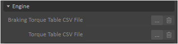
Torque Table
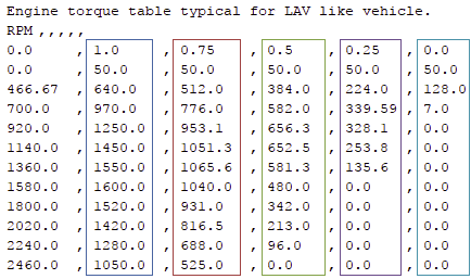
You can supply your own torque table by specifying the location of a comma-separated values (CSV) file through the Torque Table CSV File file browser parameter. Typically, this table is 10 rows by 5 columns and produces a shape similar to this: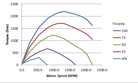
This diagram shows a typical shape for a torque table. You can see that, for a given amount of throttle, the torque increases with the revolution of the engine, reaches a maximum and then decreases. This is the normal behavior of an internal combustion engine. Also notice that for some throttle values in this example, the torque curve crosses the abscissa axis. The crossing point represents the limit for the RPM of the engine at that throttle position. If for some reason the RPM increases beyond this point, the engine brake table (therefore a resistive torque) will be used by the engine instead.
More precisely, the format of the CSV table file is as follows:
- The first row is unused, so you can use it to add comments.
- The second row identifies the contents of each column, use it for table headings. There is one label per column, separated by a comma.
Note: Labels are not used by Vehicle Systems but must be specified.
- The next row and first column are special:
- The first column specifies values of the X-axis (the RPM in this case).
- The first data row specifies the curves (the throttle in this case; e.g., 1.0 = 100% throttle, 0.75 = 75% throttle, etc.).
- The remainder of the columns specifies the values of each curve they are below in the table (the torque in this case).
- An example table may look like the following (coloured boxes added to max the values to their curves above):
Once this file has been read, a few engine characteristics are deduced from the file and given in the output container. This mainly double checks whether the table provided has been read successfully.
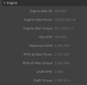
The two last entries are updated during run time, giving the current engine RPM and torque (negative value during engine braking).
The Engine component also accepts a number of inputs that can be changed during run time to control the engine’s behavior.
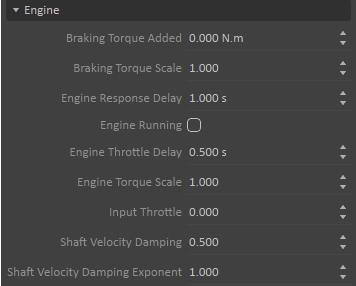
- Engine Running must be selected to turn the engine on.
- Input Throttle corresponds to the gas pedal position, its range is between 0 and 1. Note that the Throttle Logic component (if any) may take control over it.
- Engine Torque Scale is a scalar value that multiplies the torque that is read from the torque table. It is a means to adjust the power of the engine during run time. This should not be used as a way to permanently scale the table up or down. Otherwise, if the vehicle is equipped with an automatic transmission, the torque converter may not match the engine anymore and the stall speed may become incorrect.
- Engine Response Delay and Engine Throttle Delay are two ways to introduce a delay in the response of the engine. The first introduces a delay in seconds before the engine speed can change, and the second introduces a delay in the displacement of the gas pedal position.
Shaft Velocity Damping and Shaft Velocity Damping Exponent are used to add some frictional effects to the engine shaft. The friction is of the form:

where d is the shaft velocity damping, e is the shaft velocity damping exponent, ω is the actual shaft angular speed (in rad/sec) and f is the frictional force added to the shaft. The units of d and e must be such that f is in N m.
Engine Brake
The engine brake is controlled using a table containing the engine brake torque values versus the delta RPM. The delta RPM is the difference between the current shaft velocity and the desired shaft velocity. The desired shaft velocity is defined as being the RPM value that crosses the X-axis of the engine torque curve for a given throttle position.
A way to visualize the engine brake torque is to include it schematically in the drawing of the engine torque curve given in the section above as seen in the image below (the red curve).
Looking at the idle throttle curve (0 throttle position), it crosses the abscissa at around 800 RPM. This is the desired shaft velocity at that throttle. If any condition occurs that would make the engine shaft rotate at a higher speed, the engine will apply a negative torque to resist this extra velocity. For example, if the engine is about to rotate at 1300 RPM, which corresponds to a delta RPM of about 500 RPM, this would result in a negative torque of about -750 N m.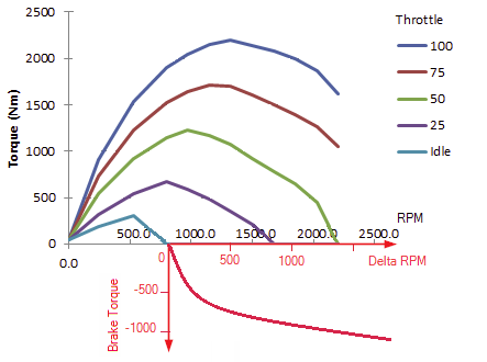
You can also specify your own torque table using the Braking Torque Table CSV File parameter.
More precisely, the format of the engine brake CSV table file is as follows:
- The first row is unused, so you can use it to add comments.
- The second row contains labels identifying the contents of the two columns.
- There is one label per column. (Labels are not used by Vehicle Systems but must be specified.)
- The next row is skipped
- Starting at the fourth row:
- The first column specifies values of the delta RPM.
- The second column specifies the value of the engine brake (negative values).
For example, the format of an engine brake torque CSV file looks like the following:
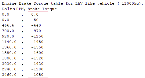
The Engine component allows control of the engine brake during run time through the two inputs, Braking Torque Scale and Braking Torque Added (accessible via the Properties panel of the Engine component). The first input is a multiplicative factor applied upon the value read from the table. The second input is added to the result.
When the engine is in braking mode, the output Shaft Torque becomes negative.
Electric Motor
An electric motor is similar to a fuel engine, but with these differences:
- A fuel engine has an idle RPM but an electric engine doesn't have any idle speed
- A fuel engine provides a maximum horsepower but an electric engine's maximum power is measured in watts
- A fuel engine spins in only one direction whereas an electric engine spins in both directions
- The torque tables for a fuel engine and an electric engine are different (see The Electric Motor's Torque Table)
- A fuel engine has an input throttle which is valid between
[ 0 and 1 ]whereas an electric motor has an input signal between[-1 and 1]
The Electric Motor's Torque Table
In the table below, the different input signals 0, 0.25, 0.5, 0.75 and 1 give the torque as a function of the motor RPM.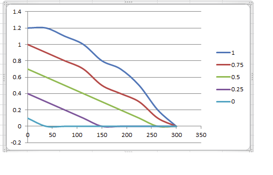
The torque table provided to the electric engine is only positive. The negative table is generated at run time by Vehicle Systems. The behavior will be exactly the same when the engine is spinning in one direction and in the other.
The Electric Motor's Brake Table
Like the torque table, the positive value is generated at run time for the brake table, when the electric motor is spinning in the other direction.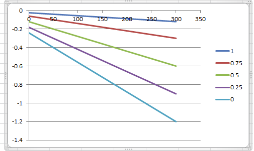
Wheels and Tracks
Wheels must be created for both wheeled and tracked vehicles.
In the case of a tracked vehicle, the wheels are the track wheels; sprockets and idler wheels are created separately.
Once the mass of the vehicle is properly set, you can start tuning the suspension stiffness and damping. Make sure that the vehicle is completely constructed and the mass completely determined before doing so. In particular, make sure that the mass of the wheels are properly set and that all accessories of the vehicle (meaning all parts have been added and linked to the chassis, such as the turret of a tank) have been constructed.
Note: We recommend adding a collision detection rule between the chassis and each wheel, to prevent these objects from colliding which would cause unwanted behavior.
Configuring Wheels
Each wheel of a wheeled vehicle has settings in the Dynamic Component's Properties page. Select the desired wheel in the relevant section to see the following fields.
- Inputs
- Brake Scale: This value is multiplied by the value in Inputs > Braking Logic > Maximum Brake Torque to determine the maximum braking torque that can be applied to the given wheel (defaults to
1.0). - Mass of the wheel (defaults to
30.0) - Material: Dynamics material of the wheel (defaults to
Wheel) - Radius of the wheel (defaults to
0.31) - Reference Point shifts the suspension's resting position (its origin) relative to the attachment point of the wheel on the chassis (defaults to
-0.08). Setting a negative value will shift the suspension origin down relative to the wheel/chassis attachment point. (Under zero load, the suspension origin is where the wheel center would end up.) - Suspension Damping: Damping coefficient of the spring-damper suspension model (defaults to
10000.0) - Suspension Stiffness: Stiffness coefficient of the spring-damper suspension model (defaults to
100000.0) - Width of the wheel (defaults to
0.22) - Steerable: Indicates whether the wheel is steerable (off by default)
- Input Angle steers the wheel. This input is calculated by the Steering Logic inputs in the vehicle's Dynamic Component Properties panel. Input Angle can be set manually if the Steering Logic component is removed in the vehicle preset file, or after de-selecting Inputs > Ackerman Steering in the vehicle's Dynamic Component Properties panel (for wheeled vehicles). See Ackerman Steering for more details.
- Suspension Highest Point and Suspension Lowest Point are the maximum and minimum points the suspension can obtain relative to the suspension origin (resting position).
- Auto Compute Inertia: Select this input to automatically compute the inertia. Otherwise, the values for Axle Inertia and Off Axle Inertia are used.
- Axle Inertia: The inertia along the axle of the wheel (in kg·m2). This value is only used if Auto Compute Inertia is not selected.
- Off Axle Inertia: The inertia along the two axes orthogonal to the axle (in kg·m2). This value is only used if Auto Compute Inertia is not selected.
- Brake Scale: This value is multiplied by the value in Inputs > Braking Logic > Maximum Brake Torque to determine the maximum braking torque that can be applied to the given wheel (defaults to
- Outputs
- Orientation: The wheel orientation in world space (in degrees).
- Position: The wheel position in world space (in meters).
- Steering Angle: The steering angle (in degrees).
- Angular Speed: The wheel's angular speed (in degrees per second).
- Material in Contact: The contact material making contact with the wheel.
- Transform: The wheel transform in world space.
- Suspension Position: The suspension position of the wheel (in meters). A value of zero means the suspension is at rest, greater than zero means the suspension is extended, and less than zero means the suspension is compressed.
- Drive Torque: The drive torque applied on the wheel by the power train.
- Parameters
- Steerable: Select this option to make the wheel steerable.
- Relative Position: The wheel's position relative to the chassis.
Configuring Tracks
Tracked vehicles require the idlers and sprockets to be defined.
There are track parts that are created to represent the track interaction with external objects, but they don't model the details of the small articulated elements of a real track. Placed between the idlers or sprockets, these provide additional grip against the terrain or against obstacles.
Tracked vehicles have one section in the Dynamic Component property page for each track where you can specify the following settings:
- Distance Between Sprocket And Idler (defaults to
3.0) - Element Local Up Direction Offset (defaults to
-0.03) - Idler Radius and Sprocket Radius (both default to
0.3) - Material (defaults to
Wheel) - Sprocket Mass (defaults to
10.0) - Track Element Mass (defaults to
30.0) - Width used during wheel creation (defaults to
0.3)
There are two types of tracks supported in Vortex®: rigid and flexible. The main difference in configuring rigid and flexible tracks is that:
- Rigid tracks use a single graphic asset to represent the entire set of road wheels, so you need to define the length ratio and thickness of the set as a whole
- Flexible tracks define each road wheel individually, so you may need to adjust each wheel's attachment and position after you have connected its corresponding graphic asset
Rigid Track Length and Thickness
To set the length ratio and thickness of the rigid tracks, set the following parameter values (under the left and right track sections of the vehicle preset's Dynamic Component property):
- Element Length Ratio (defaults to
1.0) - Thickness of the track (defaults to
0.2)
Animating Tracks
You can use a simple Python script linking the Vehicle System's linear (rigid) track displacement with the corresponding texture's UV offset. In this way, you can create an animated track.
Note The Vehicle Systems > Graphics Track extension used in older releases of Vortex is now deprecated, and should not be used anymore.
Start by inserting a Script extension in the Mechanism for each track. Then set up the following variables in each one.
- Inputs: you will receive data from the Vehicle Systems that shows the track displacement. You will need one input per track. We suggest using a variant of "Track Displacement", such as "Left Track Displacement" and "Right Track Displacement". These are of the "Real" value type.
- Outputs: you need to send the converted position data out to the track texture(s). You will need one output per track. We suggest using a variant of "Track UV Offset", such as "Left Track UV Offset" and "Right Track UV Offset". These are of the "Vector 2" value type.
- Parameters: this last value is optional but makes it easier to fine-tune the tracks' visual motion and direction. It's a scalar value that multiplies the displacement input. Again, you will need one per track; we suggest using a variant of "Track Scalar", such as "Left Track Scalar" and "Right Track Scalar". These are of the "Real" value type.
An example of the full Python script is shown below for the left track. Make sure to update the variables to correspond to the variable names you've selected, if different.
from VxSim import *

def post_step(self):
textureOffset = self.inputs.Left_Track_Displacement.value * self.parameters.Left_Track_Scalar.value
vector = VxSim.VxVector2(textureOffset, 0.0)
self.outputs.Left_Track_UV_Offset.value = (3.0*vector)
You will then need to connect the Track Displacement input of the Python script with the Vehicle Systems' "Displacement" output for the corresponding track. You will also need to connect the script's UV Offset output to the corresponding texture's "UV Offset" input. You may need to make multiple connections if there is more than one texture layer, such as Albedo, Gloss or Normal. Repeat the operation for the other track. Assuming that your tracked vehicle has a left and a right track, the two Python scripts and related connections should look like the image below.
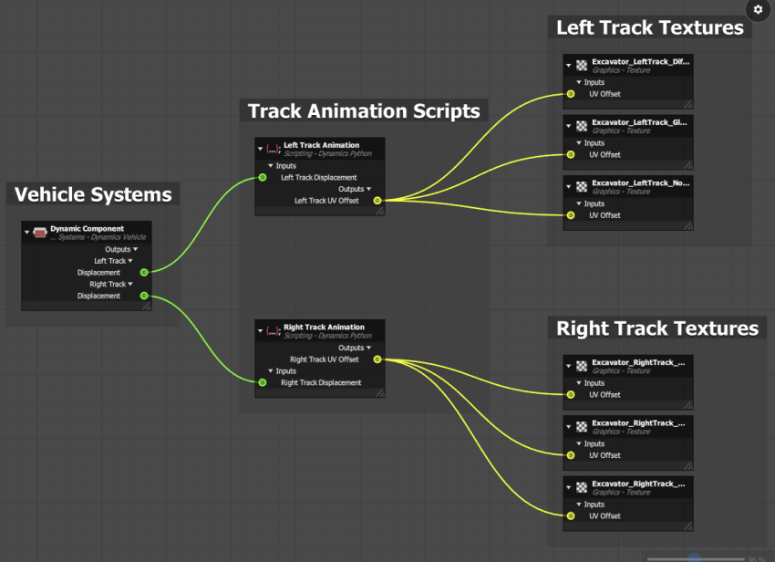
We created one script per track for clarity here, but you could use a single script for all tracks instead if preferred.
Wheel Attachments for Flexible Tracks
For each wheel defined on the wheel list of a flexible track, you can change the following parameter values (under the numbered sections of the Wheel Item List in the vehicle preset's Dynamic Component property):
- Wheel Attachment to the vehicle
- Wheel Position relative to the vehicle
Tracked Vehicle Steering Logic
In Vehicle systems, you can select one of two control methods for a flexible tracked vehicle (such as a tank): Steering mode and Pivot mode.
Steering Mode
In Steering mode, the flexible tracked vehicle drives like a car. To achieve this, the differential is locked with a specified lock ratio. This imposes the left and the right tracks to rotate at a desired speed difference which causes the vehicle to turn. The higher the ratio, the higher the speed difference and thus the smaller the turning radius.
To use Steering mode:
- Select the Dynamic Component of a tracked vehicle in the Explorer panel.
- In the resulting Properties panel, make sure that Inputs > Steering Logic > Enable Pivot Mode is not selected.
- Under Parameters > Steering Logic, specify a Steering Table CSV file (see below).
The Steering Table CSV file determines how the tracked vehicle turns. The content of the file represents a function of the form y = f(x), where x is the Input Steering value, which can be seen in the Dynamic Component's Properties panel, Inputs > Steering Logic. This x value represents the steering input displacement, normalized between 0.0 and 1.0.
The y value represents the lock ratio between the left and right tracks. A value of y=1.0 results in both tracks rotating at the same speed, and the vehicle will go straight. Thus, the first entry in the file should be (0,1). A value of y=2.0, for example, would mean the left track turns twice as fast as the right, resulting in the vehicle steering towards the right. The actual turning radius depends on the geometry of the vehicle, the linear speed of the vehicle, and the material properties of the ground.
The following are the contents of a sample Steering Table CSV file:
Steering logic table,
x,y
0,1
0.1,1.1
0.2,1.2
0.3,1.3
0.4,1.4
0.5,1.5
0.6,1.55
0.7,1.6
0.8,1.65
0.9,1.7
1,1.75
Note Only the positive x domain has to be given in the CSV files.
Pivot Mode
In this mode, differential is locked with a lock ratio of 1.0. This forces the two tracks to rotate in opposite directions. As a result, the vehicle rotate about itself. In addition, the input gear ratio of the differential is used to control the actual speed of the tracks, allowing you to control the speed of the pivot.
To use Pivot move:
- Select the Dynamic Component of a tracked vehicle in the Explorer panel.
- In the resulting Properties panel, select Inputs > Steering Logic > Enable Pivot Mode.
- Under Parameters > Steering Logic, specify a Pivot Table CSV file (see below).
The content of the user-provided Pivot Table CSV file represents a function of the form y = f(x), where x is the Input Steering value, which can be seen in the Dynamic Component's Properties panel, Inputs > Steering Logic. This x value represents the steering input displacement, normalized between 0.0 and 1.0.
The y value corresponds to the input gear ratio. A value of 0.0 results in no speed being transmitted to the tracks. A value of 2.0, for example, means that the tracks' rotational speed will be twice the speed of the input shaft of the differential. The actual speed of rotation of the vehicle depends on the geometry of the vehicle, and the material property of the ground.
The following are the contents of a sample Pivot Logic Table CSV file:
Steering logic table,
x,y
0,0
0.1,0.2
0.2,0.4
0.3,0.5
0.4,0.6
0.5,0.7
0.6,0.8
0.7,1
0.8,1.4
0.9,1.8
1,2
Note that the input shaft of the differential corresponds to the output shaft of the transmission. In general, this operation is done on the first gear where the maximum torque is available.